In the circuit shown, what can be inferred about the way the two measuring instruments are connected? 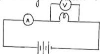
ABoth the ammeter and voltmeter are connected in series
BThe voltmeter is in series and the ammeter is in parallel
CThe ammeter is in series while the voltmeter is connected across the conductor in parallel
DBoth the ammeter and voltmeter are connected in parallel
Answer & Solution
Correct answer: C. The ammeter is in series while the voltmeter is connected across the conductor in parallel
From the figure, the ammeter $A$ lies along the main path of current, so it is in series. The voltmeter $V$ is connected across the conductor, so it is in parallel to measure the potential difference across it.
Related questions
The reactance of a capacitor $C$ at frequency $f$ in an a.c. circuit is:A bird perched on a single high voltage wire is unharmed because:The two conservation laws embodied in Kirchhoff's rules are conservation of:The resistance offered by the cell itself is called:Which device detects the current in a Wheatstone bridge?In a Wheatstone bridge, the source is connected across the:The Wheatstone bridge is made up of how many resistors?At a junction, the current entering equals the current: