Home › AP Intermediate 2nd Year › Current Electricity › Using the junction shown in the figure, which eq…
Using the junction shown in the figure, which equation correctly represents Kirchhoff's Current Law? 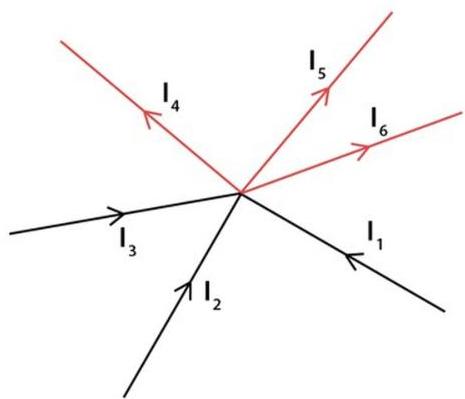
A$I_1+I_2+I_3=I_4+I_5+I_6$
B$I_4+I_5+I_6=I_1+I_2-I_3$
C$I_1+I_4=I_2+I_3+I_5+I_6$
D$I_1+I_2+I_4+I_5=I_3+I_6$
Answer & Solution
Correct answer: A. $I_1+I_2+I_3=I_4+I_5+I_6$
From the arrows in the figure, $I_1$, $I_2$, and $I_3$ are directed toward the junction, while $I_4$, $I_5$, and $I_6$ are directed away from it. Hence, by Kirchhoff's Current Law, $I_1+I_2+I_3=I_4+I_5+I_6$.

Related questions
The reactance of a capacitor $C$ at frequency $f$ in an a.c. circuit is:A bird perched on a single high voltage wire is unharmed because:The two conservation laws embodied in Kirchhoff's rules are conservation of:The resistance offered by the cell itself is called:Which device detects the current in a Wheatstone bridge?In a Wheatstone bridge, the source is connected across the:The Wheatstone bridge is made up of how many resistors?At a junction, the current entering equals the current: