A waveform shown when applied to the following circuit will produce which of the following output waveform. Assuming ideal diode configuration and $R_{1} = R_{2}$ 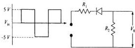
A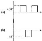
B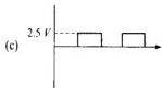
C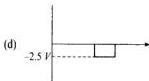
D
Answer & Solution
Correct answer: D.
For the positive level of input, the diode is reverse biased because its cathode is toward the input side through $R_1$ and its anode is at the output node. So the diode is OFF, and the output node is connected only to ground through $R_2$. Hence $V_o=0$ during the $+5\,\mathrm{V}$ intervals.<br><br>For the negative level of input, the left side becomes at lower potential, so the diode is forward biased and acts as a short. Then $R_1$ and $R_2$ form a voltage divider from $V_{in}$ to ground, with output taken at their junction.<br><br>Thus, for $V_{in}=-5\,\mathrm{V}$ and $R_1=R_2$,<br><br>$$V_o=\frac{R_2}{R_1+R_2}V_{in}=\frac{1}{2}(-5)=-2.5\,\mathrm{V}$$<br><br>So the output is zero during positive pulses and $-2.5\,\mathrm{V}$ during negative pulses. Among the given options, this matches option $D$.
Related questions
In gamma decay, what is emitted?A positron has the same mass as an electron but a charge that is:In beta decay, which particles may be emitted?In alpha decay, which nucleus is emitted?How many types of radioactive decay occur in nature?Radioactivity is a decay undergone by a nucleus that is:Becquerel's emission penetrated black paper and:Becquerel made his discovery while studying: